 |
| Image 1 To begin, a master bent is made that represents the largest one that is going to be in the trestle |
 |
| Image 2 Drawing of bent that will be used as a template with which future bents will be made. |
 |
Image 3
Wood pieces are then glued into place for the fixture. This will be the guide for all bents so they will be the same whether they are short or tall.
|
 |
| Images 4 through 8 Vertical timbers are now being placed in the fixture wood guides . The guide makes sure all timbers are consistent for each one that is built. |
 |
| Image 5 |
 |
| Image 6 |
 |
| Image 7 |
 |
| Image 8 |
 |
| Image 9 Dots of white glue are added. |
 |
| Image 10 Cross member placed on white glue. Allow the glue to dry completely. |
 |
| Image 11 Cross members now in place on one side. |
 |
| Image 12 Wood pieces added to fixture for placement |
 |
| Image 13 Horizontal supports |
 |
| Image 14 Horizontal pieces cut to fit and ready to install. |
 |
| Image 15 White glue added where horizontal pieces will go. |
 |
| Image 16 Wooden supports are now added. |
 |
| Image 17 Bent is removed from fixture and is now ready for supports. |
 |
| Image 18 Glue spots now put on back side of bent. |
 |
Image 19
Lamenting Stringers
Three thin pieces of wood are lamented together to form stringers. By lamenting three pieces together you are able to bend stringers to match your radius.
|
 |
| Image 20 |
 |
| Image 21 |
 |
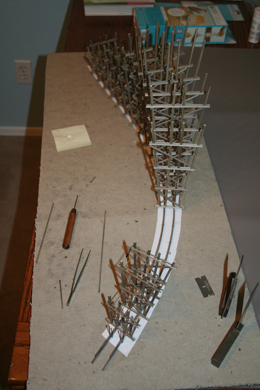
| Images 22 through 27 The assembly of the trestle begins upside down, one bent at a time. Each bent is glued into place in an upright position and allowed to dry. |
 |
| Image 23 |
 |
| Image 24 |
 |
| Image 25 |
 |
| Image 26 |
 |
| Image 27 |
 |
| Images 28 through 32 Horizontal supports are glued in place to help support trestle bents as they are mounted one at a time. |
 |
| Image 29 |
 |
| Image 30 |
 |
| Image 31 |
 |
| Image 32 |
 |
| Images 33 and 34 Trestle removed from homosote and placed upright for the first time. |
 |
| Image 34 |
 |
| Image 35 End bents sheathed with wood to keep dirt from flowing in. |
 |
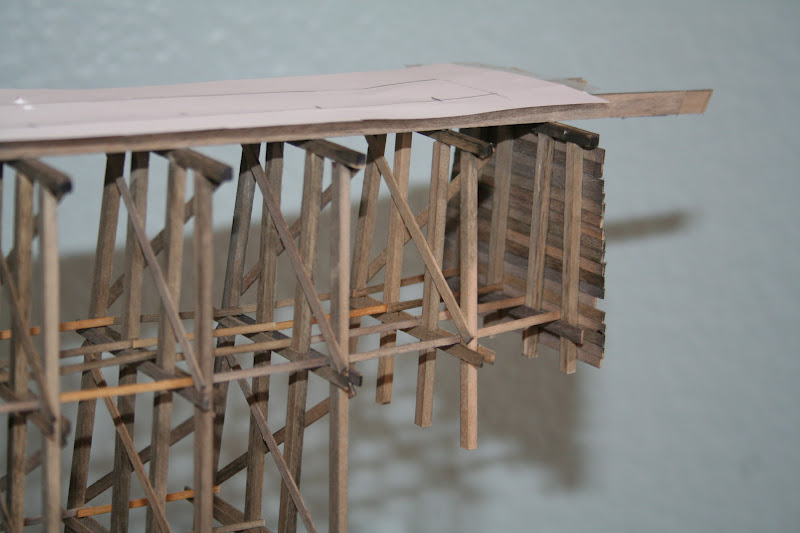
| Images 36 and 37 Stringers on top of trestle to which ties will be added, stringers are directly under rails for support. |
 |
| Image 37 |
 |
| Images 38, 39 & 40 Ties are added to the top pf the stringers, rail to come later after the trestle is mounted on the support structure. |
 |
| Image 39 |
 |
| Image 40 |
very nice and informative
ReplyDelete